AMSAT OSCAR 40 Briefing

Maggie Leber K3XS
Editor, Phil-Mont Mobile Radio Club The Blurb
k3xs@arrl.net


Maggie Leber K3XS
k3xs@arrl.net
This illustrates the relative sizes of AO-40 and previous recent amateur radio spacecraft. You can see that there's room for a lot more on AO-40, and that room was all used.
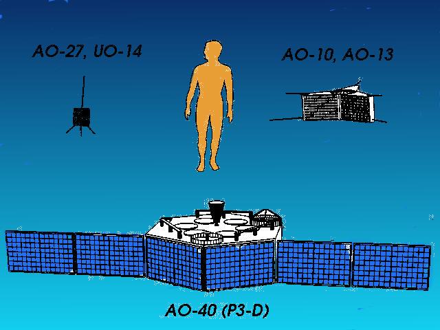
The big spaceframe and large amounts of available power made it possible to include a lot of systems in Phase 3D design. ("Phase 3D" was the pre-launch designation for the satellite that was designated AMSAT OSCAR 40 upon acheiving orbit)
Here's a matrix with an entry for every major system on the spacecraft, with an indication of its staus as of this writing. You can see that AO-40 was a very ambitious design...and the large number of systems marked "+" for "functional/operational" show us that AO-40 is far from dead.
(Cheerfully stolen fromhttp://www.amsat.de)
| IHU-1 computer | + | RF-RX | ? | V-TX | - | RUDAK-A | + |
| IHU-2 computer | + | V-RX | + | U-TX | # | RUDAK-B | + |
| Magnetorque Coils | + | U-RX | + | S1-TX | # | SCOPE-A Camera | + |
| Earth/Sun-Sensors | + | L1-RX | + | S2-TX | + | SCOPE-B Camera | + |
| Momentum Wheels | \ | L2-RX | + | X-TX | - | YACE Camera | + |
| 400N Thruster | / | S1-RX | + | K-TX | + | Cedex | + |
| ATOS Thruster | / | S2-RX | - | Laser | ? | GPS | + |
| Solar Array. | + | C-RX | - | LEILA-1 | + | RF-Exp | ? |
| Omni Antennas | # | IF-Matrix | + | LEILA-2 | + | Smart Node | + |
A "Molniya" high eccentricity orbit gives long pass times and low angular rates vs. Low Earth Orbit (LEO) birds. A typical "good" LEO pass is less than 15 minutes horizon to horizon AO-40 will hang in your sky for many hours at a time.
(diagram of eccentricity and inclination)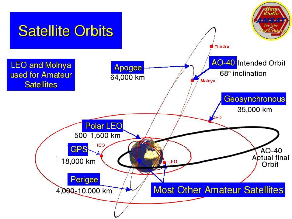
The 400n thruster was intended to reshape the basically equitorial geosychronous transfer orbit (GTO) provided by the Ariane V booster to an orbit with more inclination angle--about 63 degrees--to the equator, resulting in the satellite moving further to the north and south. The apogee was planned to be around 47,700 km and the perigee 400-10,000 km. This would have resulted in an "orbital mean" of 16 hours, resulting in a ground observer getting approximately the same pass every 16 hours. Three-axis stabilization provided byinertia wheel attitude control would provide three-axis stabilization, resulting in optimum pointing of spacecraft antennas and the solar panel array.
Unfortunately this design orbit isn't what we ended up with.
AO-40 experienced an on-board explosion shortly after the first use of an on-board rocket engine. This disabled a number of on-board systems, and resulted in a spacecraft that was significantly less capable than originally hoped. Nonetheless, there's still more bandwidth available through AO-40 than in all the other amateur satellites put together.
The period of AO-40's orbit is about 19 hours 6.5 minutes. In four days a total of just over five orbits complete, and, at the observer, it appears that almost the same conditions exist as four days previously. The sub satellite point at apogee is oscillating between 7.6º north and 7.6º south. far from the 68º inclination originally desired.
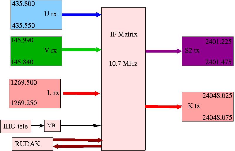
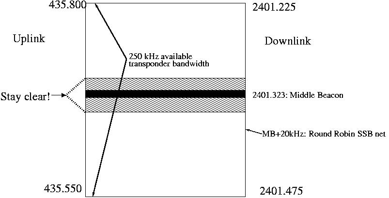
The IF matrix allows the IHU to command the connection of signal sources, like uplink recievers, beacons and on-board digital modulators to destinations like downlink transmitters and digital demodulators. It has a lot of flexibility, and the schedule for IF matrix configurations is published in the telmetry N-blocks by the command team. (The N block is also available at http://amsat-dl.org)
Here's a partial diagram of the IF-matrix showing the operationally important elements; refer to the decoded telemetry A-block for a depiction of the entire matrix.
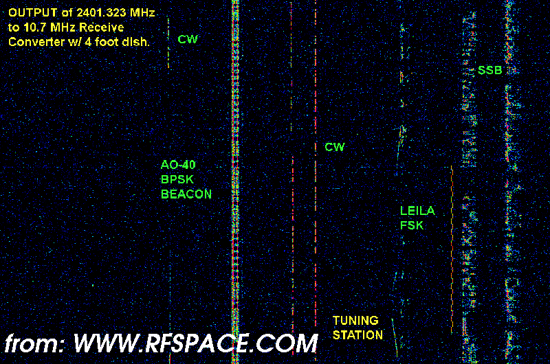
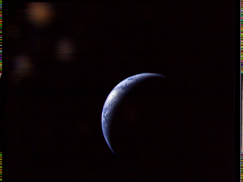
The two on-board camera experiments have provided assistance in measuring the spacecraft attitude in orbit, as well as some of the more spectacular images recieved from an amatuer-built spacecraft:

Also tested and known to be operational:
If this system can be comissioned, the spacecraft will hold an optimum attitude throughout each orbit, keeping antennas pointed towards the Earth and solar celle pointed to the Sun. This will improve "squint angles" and power availability to the spacecraft systems. Once the attitude control system is fully operational, the solar panels wings can be unfolded; currently they are wrapped around the spinning spacecraft.
Work on this has proceeded slowly because the original plans, calculations and programming had beed designed for the design orbit, rather than the lower-inclination orbit that actually resulted. Work by the command team is slow and careful because an error or equipment failure on-board could cause the spacecraft to be lost.
RUDAK is a pair of fully programmable computers, each of which has its own memory and associated hardware modems and DSP modems. It also controls many of the experiments on AO-40: GPS receivers, the SCOPE cameras, two sets of temperature telemetry nodes, the MONITOR HF passive sounding experiment, and the CEDEX radiation experiment.
RUDAK is still in the process of comissioning; some undesired and unanticipated interactions between the RODAK and the other components on board make it impractical to operate RUDAK and the linear transponder systems at the same time.
Think of it as a programmable packet BBS with software-defined transceivers on steroids in orbit...
This is the most commonly used downlink band. It's most often received through a downconverter or pre-amp/downconverter combination, using 2m or 70cm as the IF. Typical antennas are helixes and small dishes. QST recently published an S-band horn antenna design made from a cardboard box.
S-band is indeed microwave, but it's not difficult to receive, with only a little bit of additional equipment added to an all-mode VHF or UHF receiever.
Today's general coverage VHF receievers can even use a slightly-modified or even unmodified surplus Multichannel Multipoint Distribution Service (MMDS) downconverter to receive S-band signals. These are available though amateur channels
The most common uplink band. Many amateur Earth stations already have UHF transmitter systems.
A compact numerical description of a satellite's orbit, used for making orbital pass predictions. Usually revised over time to match the observed positioon of the satellite. Commonly called, "keps", they are available by email, FTP or on the web. They do *not* include satellite attitude information, necessary to calculate the "squint angle", or spacecraft antenna pointing information
They look like this in NORAD format, the most commonly used:Current Keplerian orbital elements are available from a number of sources, including ARRL bulletins and the AMSAT and Celestrak websites.
SatTrack V3.1                 AO-40 TRACKING DISPLAY                          K3XS

Ground Stn :  Jeffersonville   Now: Sun 11May2003   Downlnk S2MB:  2401.3230 MHz
Satellite  :        Oscar 40   131  21:52:18  EST   Uplink  NONE:     0.0000 MHz
Inclination:       8.523 deg                        Downlnk Loss:     0.0000 dB
Orbit      :  1163  72.5 % D   Object  :    26609   Uplink  Loss:     0.0000 dB
Sun   Az/El: 326.9 -25.1 deg   Model   : TLE Mean   Squint Angle:   124.3270 deg
Moon  Az/El: 213.8  51.3 deg   Tracking:      OFF   Phase ( 256):   185.5100 U+MB

     Azimuth   :      306.250 deg            Latitude     :      1.491 deg N /
     Elevation :      -38.452 deg \          Longitude    :    147.013 deg E
     Range     :    59599.503 km             Height       :  49483.656 km
     Range Rate:       -1.115 km/s           Velocity     :      1.813 km/s

State Vector  X: +28292.707 km        Y: +48145.153 km        Z:  +1451.939 km
             VX:     -1.753 km/s     VY:     -0.437 km/s     VZ:     +0.158 km/s

      Next AOS  : 132/03:23:18 EST            AOS Azimuth  :    178.600 deg  V
      Duration  :   0/15:26:24                MEL Azimuth  :    184.000 deg  D
      Next LOS  : 132/18:49:41 EST            LOS Azimuth  :    267.200 deg  D
      Countdown :   0/05:31:00                Max Elevation:     44.300 deg
                                              MEL Range    :  59799.300 km

      Ground Track: QJ31ML     620.5 km NNE of Wewak, Papua-New Guinea
|
http://www.amsat-dl.org/p3d/tlmspec.txtA "Message of the Day", followed by 128 analog and 128 digital telemetry channels
A  HI, THIS IS AMSAT OSCAR-40       2003-05-11  20:53:14  #0975
+--------------------------------------------------------------+
|  Hgt: 57420 km   Lon: -146  Lat: -1   ALON: 330  ALAT: 24    |
+--------------------------------------------------------------+
..........$@.?)b,)+.....&&.....CCM.4Q....MH)&...........wM..-Nw.
}......!..}yf{{{zg..}@.......@..@~}}}......}...}311112112""Z""""
..........@......Z.e m.....5.2...M..%j....5.-$..................
~_~_~_Q......p..X........B...x..u...... ............. .0.@.P.d.p
|
The telemetry channels are more easily understood when decoded with software, but are probably of interest mostly to the command team and deep AO-40 fans:
K Whole Orbit Data V1.2 Samples: 1 Captured Channel: #019B gggggg.......................................................... .......................................;;;....;;................ ............... ............;;...;;.....;.;.;.;;............. ................................................................ ........................;;;...;;....wwwwww................gg.... ....... |
M  QST AMSAT OSCAR-40                                2003 May 11

  ALON/ALAT ~ 330/25.  Holding ALON and slowly lowering ALAT.
      Passband off for ~ 1 more week.  Beacon remains ON.

         The AO-40 team would like your telemetry files!
Please "zip" compress your daily telemetry files and e-mail to:
                      ao40-archive@amsat.org
|
N is used to publish the transponder schedule, showing what systems are operating in what part of the orbit, expressed in "mean anomaly" 0->255, zero being perigee.
N  QST AMSAT AO-40          SCHEDULE                2003-03-25
               MA      010   120   240   244   010
               ---------7-----1-----5-----0-----7
               S2/K-Tx  |  S  |  S  |  S  |  S  |
               MB       |  *  |  *  |  *  |  *  |
               RUDAK    |     |     |     |     |
               V/U-Rx   |  U  |  U  |  U  |  V  |
               Uplink   |     | UL  |     |     |
|